SHISHAM Products - lifting equipment comes as a complete package:
VOID
LIFTER
SHEAR BARS
TENSION BARS
STRUCTURAL FERRULES and
LIFTING CLUTCHES to suit all products
For further information contact us at: (03) 9791 4622
Or visit our website at: www.shisham.com.au
All data provided in this catalogue is based on current technical specifications as represented in the Australian Standards AS 3600, AS1170, As1310, AS1311,AS1315,As1379,AS1250,AS1418 parts 1,2,3,5,&7. AS1480,AS1481,AS1510,AS1554,AS2121 and AAS3850 parts 11to 3 at the time of publication.
All items shall be used in conjunction with the approved shop drawings and design engineers specifications.
We reserve the right to make technical and design changes at any time.
Shisham Products provides this data in good faith and does not accept liability for the accuracy of the information in the publication or for any errors in the published data.
SHISHAM Products have been in the building industry for over 20 years, supplying Precast and Tiltup manufacturers with total packages for the construction of reinforced concrete panels.
The SHISHAM universal lifting systems are reliable and easy to install, and over this period have proven safe, reliable and time saving for manufacturers, contractors and erectors of these concrete building systems.
The plate and bar used in the manufacture of SHISHAM Universal Anchors is selected by grade for weight, for each application. They are manufactured with a minimum safety factor of 2.5 in accordance with Australian Standard AS 3850.
They are precision engineered using the latest technology, to provide the most cost effective product for today's market place. Products are available in black steel, zinc chromate finish or are hot dipped galvanised to AS 1650-1989.
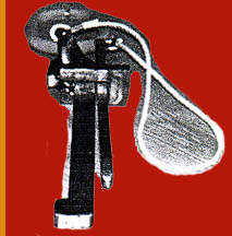
Face Lifter Models
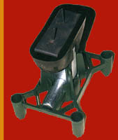
The SHISHAM Face Lifters are modular
assemblies complete with disposable plastic void former, support legs and cross-bar, and are suitable for panel thickness from 150 to 200 mm, and 5 tonne lifting capacity. Shear bars are fitted according to designer's specification, but should be -Y12 x 300mm or Y12 x 500mm for panels 100 to 150mm thick
Y16 x 300mm or Y16 x 500mm for panels above 150mm thick.
The Face Lifter is used primarily for tilt panel lifting. The anchor is located face up in the panel prior to the concrete pour. The void
former has arrows for lining up the unit in the direction of lift,
top-to-bottom of the panel. Lifting points will be specified by the design
engineer.
Edge Lifter Models in sizes 2.5, 5.0 and 10.0 tonne
These lifting and erection anchors are designed for lifting, tilting and rotating precast panels at the manufacturing and erection sites.
There are three anchor types used in this range -
2.5 and 5.0 tonne
10.0 tonne
2.5, 5.0 and 10.0 tonne
|
'Hairpin'
'Structural'
'Two-hole'
|
for edge lift and rotation
for edge lift and rotation
for thin panels and straight lift units
|
The Hairpin and Structural anchors have their own built-in tension or pullout capacity by virtue of their shape. The addition of the reinforcing shear bars for angle lifting and rotation, adds further
tension capability. The preceding pages therefore cover all aspects of the application of these anchors.
The Two-hole anchor is specially designed for horizontal to vertical edge pulls and shear rotation of thin-walled units. As with the Hairpin and Structural anchors, notches on the sides of the anchor accept shear bar reinforcement for spall-free panel rotation in edge lifting applications. For direct
lifting applications the tension reinforcement is sufficient to develop full pullout load capacity.
The V shaped tension bar is fitted through the second hole and is cast well into the concrete body of the panel. The following diagram and tables describe the anchor, its load capabilities and erection reinforcement requirements.
Void former creates clearances for universal clutch application, giving angular lifting freedom and load capacity effects as indicated in the following diagram -
The Hairpin and Structural anchors are shaped so as to transfer tension or pullout loads to the concrete structure. The Two-hole anchor relies on a Tension bar or spread anchor reinforcement for this load transfer as per the following diagram and table -
Shear
For lifting and rotating panels, the following design of shear bar assembly is mandatory.
With 'erection' reinforcement placed on both sides of the anchor this also acts to increase tension or pullout load capacity, to the extent that no additional tension reinforcement is required for the Hairpin and Structural anchors to achieve full load capacity.
Notes to diagram above and table below
- Dimension H depends on thickness of the panel/unit, the erection reinforcement should be placed within the unit reinforcement area.
However, there is a minimum dimension for 'H' as indicated.
- Erection reinforcement bar length before bending 'L' is given.
Reinforcement steel is Rebar 500 of diameter 'F' as shown.
- Bar bending radius is according to AS 3600.
- Concrete strength must be not less than 15 MPa, refer AS 3600.
- Anchors must not be reworked, by welding or any other process, either during construction or lifting.
Load Group
(t)
|
Erection reinforcement
Rebar 500' x L'(mm)
|
'H' Minimum
(mm)
|
|
2.5
|
12 ø x 800
|
50
|
|
5.0
|
16 ø x 1000
|
75
|
|
10.0
|
20 ø x 1500
|
115
|
|
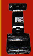
Structural anchors
are of 10 tonne
pullout capacity,
and are made of
20mm thick plate,
of Grade 350 steel,
and are 305 mm long. |
 |
The Structural anchor has two steel protrusions on the head of the anchor to provide added protection against spalling. These protrusions limit the sideways movement of the 'Universal' ring clutch, to give added support when the pull is lateral.
|
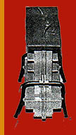
Reinforcement
Shear bars are provided as
per the previous pages.
A tension bar is fitted
through one of two holes in
the anchor, not the slotted
hole used for the clutch.
The tension bar provides
capacity for edge tension lifts up to
the full tension capacity of the anchor.
|
 |
Note on load calculation for panel manufacturer
Lifting a panel from the mould requires consideration of four (4) load components -
- Deadweight: the as-cast weight of the unit 'G'
- Mould release: 'M' allowing for adhesion to the mould, dependent on treatment and surface finish of the mould, usually calculated from a load per unit surface area x mould contact area
- Dynamic loads: making allowance for the lifting acceleration of the crane; a multiplying factor to apply to (G + M), varying from 1.1 to 2.2, depending on the quality of the lift (crane type) and the speed of the crane. When using an excavator for transporting precast units on an uneven surface, this must be at least a factor of two (2).
- Angle of lift: a multiplier for (G + M), varying from 1 to 2, for the angle from the vertical 'B', in the range -
Angle of lift B
(degrees)
|
Multiplier
|
|
0
|
1.00
|
|
7.5
|
1.01
|
|
15
|
1.04
|
|
22.5
|
1.08
|
|
30
|
1.16
|
|
37.5
|
1.26
|
|
45
|
1.41
|
|
52.5
|
1.64
|
|
60
|
2.00
|
|
These additions and multiplications yield a total load, to be divided by the number of anchors to determine single anchor loads.
This leads to consideration to lifting tackle and arrangements.
Irregular shaped panels require consideration of centre of gravity and moments to determine individual anchor loads.
|
Notes for all users
- Consult the relevant Australian Standards when using these products.
- Panels/units must be built to design engineers approved shop drawings.
- Check all parts of the lifting clutch, for damage and function, before use.
- A minimum factor of safety of 2.5 is applied to anchor pullout from concrete
in accordance with AS 3850.
M&M Concrete Lifting System
23 Attenborough Street, Dandenong, 3175
Phone: (03) 9791-4622 Fax: (03) 9792-4854
M & M Lifters a Totally Non Corrosive Application Product
M & M lifters and their associated ferrules with stainless steel nuts and spacers are made from high quality plastics. Used in normal application and areas where corrosion or staining may take place. Architectural are where these products have extensive use.
The M & M Lifters come in both face and edge lifter models. They use their own specific designed clutch for lifting. These clutches are available from Shisham Products exclusively.
|
Safe Working Loads (Tensile) for 1500 Panels
|
|
10 Mpa
|
15 Mpa
|
20 Mpa
|
25 Mpa
|
30 Mpa
|
|
20 Kn
|
30 Kn
|
34 Kn
|
38 Kn
|
42 Kn
|
|
Safe Working Loads (Shear) for 1500 Panels
|
|
10 Mpa
|
15 Mpa
|
20 Mpa
|
25 Mpa
|
30 Mpa
|
|
9 Kn
|
11 Kn
|
13 Kn
|
15 Kn
|
17 Kn
|
Ratings are based on minimum corner distance 750mm
Spacing between anchors 150mm
Please note: Voids must be fitted central in panel thickness to gain Max S.W.L. with a shear bar fitted.
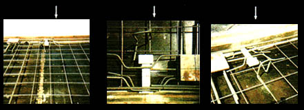
M & M Concrete Lifting Systems
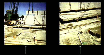 |
Panels ready for lifting with safety clutches in position.
|
|
Edge lifting inserts are placed in form work with two front shear bars and one rear shear bar, single mesh and perimeter bars.
|
 |
Void Installation Instructions for Edge Lift Voids in Panels
M & M Clutch System
Safe Working Loads (Tensile) for 1500mm Panels
Factor of safety 3 to 1
|
|
10 Mpa
|
15 Mpa
|
20 Mpa
|
25 Mpa
|
30 Mpa
|
|
20 Kn
|
30 Kn
|
34 Kn
|
38 Kn
|
42 Kn
|
|
Safe Working Loads (Shear) for 1500 Panels
|
|
10 Mpa
|
15 Mpa
|
20 Mpa
|
25 Mpa
|
30 Mpa
|
|
9 Kn
|
11 Kn
|
13 Kn
|
15 Kn
|
17 Kn
|
Ratings based on minimum corner distance 750mm
Spacing between anchors 1500mm
Please note: Voids must be fitted central in panel thickness to gain Max S.W.L. with a shear bar fitted
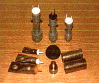
Structural Fixing Ferrules
|
Round cross hole drilled.
Test results available.
Manufactured from grade S1214 steel and finished with zinc plating.
Y12 x 300mm cross bars must be inserted through ferrule to obtain these loads.
|
 |
Ultimate Tensile capacity in Kn, over a range of concrete strengths
| Concrete Strength MPA |
M12x65 |
M16x75 |
M20x75 |
M20x95 |
M20x100 |
|
15
|
16.9
|
21.8
|
22.7
|
34.9
|
34.9
|
|
20
|
19.3
|
24.2
|
26.2
|
40.1
|
40.1
|
|
25
|
20.0
|
28.7
|
29.2
|
44.2
|
44.2
|
|
30
|
23.7
|
32.0
|
32.1
|
48.7
|
48.7
|
|
40
|
26.0
|
35.7
|
35.7
|
54.0
|
54.0
|
|
Outside Diameter
|
22
|
28
|
28
|
28
|
28
|
|
Also Available:
|
|
Hot Dip Galvanised Finish
|
Nailing Plates
|
|
Screw in Caps
|
Antenna Caps
|
All data shown is from supervised test conducted on behalf of Shisham Products by licensed NATA testing authorities and issued in good faith but without affecting any warranties. Technical data is subject to change without notice.
Transport and Handling:
In relation to the transport and erection of the panels the design engineers application charts should be followed.
All panels should be erected in the sequence of the design engineer's chart. Selection of the designated clutch must be based on the design engineers chart and weight loads to be applied.
All supporting Props should be in place prior to lifting of the panels , their weight should be included in the mass calculations.
All of the above requirements should be as per Australian Standards AS3850 and the Victorian Code of Practice for Tilt Up Construction.